Introduction to Mode Field Diameter (MFD) in Hyperscale and AI Data Centers
Mode Field Diameter (MFD) plays a crucial role in Single-Mode Fiber (SMF) data center deployment. Drawing insights from AFL's comprehensive white paper on the theme, this article looks at the relationship between MFD and optical fiber performance, providing valuable insights for designers, installers, and operators at all experience levels. Understanding these concepts is essential for optimizing network reliability, efficiency, and scalability in today's data-intensive environments.
What is MFD?
MFD is the effective diameter of the optical power distribution in single-mode fiber. Note that MFD typically expands somewhat beyond the light-carrying core into the cladding region; therefore, core diameter and MFD are not the same. Whereas core diameter is literally the diameter of the optical fiber core, MFD refers to the area of the fiber through which light signals propagate, including a portion of the cladding.
What is MFD Mismatch?
Why does this difference between core diameter and MFD matter when understanding MFD in the data center?
Fiber MFD will vary due to design differences across fiber types and manufacturers. It is important to note that MFD variation can also be experienced for fibers of the same type and manufacturer, generally over the full tolerance range allowed by the standards.
Joining fibers of different MFD by splicing or connecting can introduce optical effects that should be understood by network designers and installers. These include:
- Insertion loss (IL) associated with imperfect optical coupling across the joint. This loss is small for fibers with standards-compliant MFD and increases with greater MFD difference. See the white paper for more details.
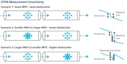
- OTDR measures artifacts due to differences in backscatter characteristics of the two fibers. Backscatter is primarily a property of the glass itself but can vary with MFD. Differences in backscatter across a joint can lead to apparent increased loss or gain as “seen” by an OTDR but have no measurable impact on optical power level at the receiver.
Standards Governing MFD Specifications
The ITU-T industry standards define acceptable MFD ranges to ensure interoperability and performance consistency. For example, ITU-T G.652 standard single-mode fibers typically have an MFD range of 8.6 to 9.5 μm with a tolerance of ±0.6 μm, while G.657A.1 bend-insensitive fibers have a nominal MFD range of 8.6 to 9.2 μm with a tighter tolerance of ±0.4 μm. Adherence to these standards is crucial for ensuring that fibers from different manufacturers can be effectively integrated within the same network infrastructure.
MFD in Hyperscale and AI Data Centers
In hyperscale and AI-focused data centers, the choice of fiber with appropriate MFD characteristics is important. Data center fiber requirements are different from those of telecommunications.
Impact of MFD on Bend Sensitivity: Bend sensitivity is a critical consideration in data center fiber installations. Data center internal networks (“white space”) and campus links (data center interconnect or DCI) run at 1310 nm wavelength. At this wavelength, bend loss for all G.652 and G.657 fibers is very low.
Fibers with larger MFDs are more susceptible to bend-induced loss because the optical field extends further into the cladding, which can cause increased loss when the fiber is bent. Choosing a lower nominal MFD and keeping tighter production control can minimize bend sensitivity without resorting to more complex and expensive trench containment fiber design.
In practical terms, this means that during installation and maintenance, careful attention must be paid to the minimum bend radius specifications of the fiber. Utilizing fibers designed with optimized MFDs can mitigate bend losses, ensuring consistent performance even in densely packed or constrained routing scenarios common in hyperscale data centers.
Other MFD related Considerations: Larger MFD can reduce fiber attenuation over distance. This is important for telecommunications for which long fiber spans are common but much less significant, particularly in the white space. MFD has a minor impact on chromatic and polarization mode dispersion.
MFD's Role in Optical Testing
Optical Time Domain Reflectometer (OTDR) testing is a standard method for characterizing fiber optic links. However, differences in MFD between fibers can affect OTDR measurements. OTDR measurement works by injecting a short pulse of light into one end of a fiber link and observing the light returned to the same end over time. Light is returned to the launch end by reflection and backscatter.
Reflection is caused by an optical discontinuity in the link, for example, at a point of connection with debris preventing full glass-to-glass contact. Backscatter is caused by interaction with particles and discontinuities in the glass that are smaller than the wavelength of the light. Backscatter provides the signal that an OTDR uses to monitor conditions along the fiber path, a kind of optical radar. If the intensity of the backscattered light falls at a point along the path, that is interpreted as a loss (IL) at that point.
Backscatter is primarily a property of the glass itself but can vary with MFD. Differences in backscatter across a joint can lead to apparent increased loss or gain as “seen” by an OTDR but have no measurable impact on optical power level at the receiver.
Backscatter of different fibers is different. OTDR monitoring may show a difference in backscatter returned light from one side of a joint to the other. If the level returned from the far side of a joint is higher, this is called a "gainer" (false increase in signal level) or "excess loss” if the level is lower on the far side due to backscatter difference. This is an instrumental effect and does not indicate a change in the level of light passed forward across the joint.
Understanding the MFD characteristics of the fibers under test is vital for correct OTDR interpretation. Technicians must consider these factors to distinguish between actual faults and artifacts caused by MFD mismatches, ensuring reliable assessment of the network's health.
In data center applications it is strongly recommended to use optical light source and power meter test methods to qualify fiber links. This provides a true measure of the ability of a link to deliver optical energy and most closely aligns with in service transmit and receive performance.
OTDR testing is particularly useful for troubleshooting and can be used to establish a baseline “as installed” optical profile. If used for qualification testing, bidirectional measurement is essential to assure reliable IL results.
Conclusion
Mode Field Diameter (MFD) is a fundamental parameter that influences many aspects of fiber optic network performance, including bend sensitivity, insertion loss, and OTDR testing. In the context of hyperscale and AI data centers, where high-density and high-performance networks are essential, a thorough understanding of MFD enables informed decisions in fiber selection, installation practices, and maintenance procedures. By understanding MFD considerations, data center professionals can optimize network performance, reliability, and cost.
About the Author

Alan Keizer
Dr. Alan Keizer is Senior Technical Advisor for AFL Hyperscale. Alan earned a Ph.D. in Physics from Cornell University and has worked at the intersection of computers and networking for the past four decades. He has been an individual technologist, a business development leader and senior executive. Joining FibreFab in 2006, he was a key contributor to the business which was acquired by AFL Telecommunications in 2013 and became a key component of today’s AFL Hyperscale. Since 2010, his main focus has been development of optical fiber connectivity solutions for hyperscale computing.


