Design Considerations for Liquid Level and Flow Sensors Data Center Cooling

Data center cooling system designers evaluating liquid level sensors and flow detection solutions often need straightforward, reliable, and cost-effective sensor technologies for their applications. Three of the most widely used methods are:
- Float-type level sensors (magneto‑reed switch devices)
- Optical liquid level sensors (infrared LED + photodiode with conical prism)
- Flow sensors (Piston type, reed switch sensors)
This article is intended to assist designers and engineers with understanding when to use each sensor type, key design considerations, integration challenges, and performance tradeoffs so they can select the right technology for tanks, reservoirs, tubing, pumps, and fluid management systems.
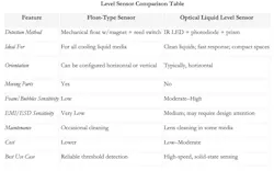
Overview of Float-Type vs. Optical Level Sensors
Float-Type Point Level and Continuous Liquid Level Sensors
How they work:
A buoyant float moves with liquid level. Magnets inside the float actuate a reed switch (or a series of reed switches and resistors for continuous) inside a sealed stem.
Typical applications:
- High/low coolant tank alarms
- Pump protection (low-level cutoff)
- Continuous coolant tank level indication
Key advantages:
- Simple, robust, and low cost
- Passive operation (single point reed switch devices require no power)
- Highly resistant to EMI noise
- Reliable in all types of fluids
- Continuous sensors can provide a 1-5 VDC or 4-20ma output for system level monitoring
Key limitations:
- Contains moving parts (wear or sticking possible)
- Sensitive to orientation
- Can be affected by debris, viscosity, or turbulence
- Continuous reed-based level sensors provide output with a resolution, typically every ¼”
- Higher resolution sensors are available
Optical Liquid Level Sensors
How they work:
An IR LED shines a light beam into a conical prism tip.
- In air: IR light internally reflects into the detector via the prism indicating a “dry” condition.
- In liquid: the refractive index changes and light escapes into the liquid, indicating a "wet" condition.
Typical applications:
- Small reservoirs with tight spaces
- For use in clear or translucent liquids
Key advantages:
- No moving parts
- Very fast response (<1 ms)
- Long service life
Key limitations:
- Can be sensitive to bubbles, foam, and optical contamination
- Can get “fooled” by a reflective surface near the prism (Typically <2”)
- Requires power and proper EMI design consideration
- Sensor has a limited electrical load or output capability.
- Suitable for most TTL logic applications
Design Considerations for System Integration
Mechanical Considerations
Float Sensors
- Mounting orientation:
- Vertical stem designs are configured at desired set points.
- Horizontal or side mount units can be employed at desired tank levels through tank wall fittings.
- Setpoint accuracy: Defined by float geometry and stem length
- Is typically +/- 1/8” (3mm) for single point and +/- ¼” resolution for continuous
- Slosh and turbulence: Add baffles or stilling tubes around the float, if needed.
- Material compatibility: (Stem and float choices can be different, per application)
- Water:
- Consider PVC, polypropylene, polyethylene polymers or 316 stainless steel
- Non-conductive cooling media (i.e. 3m Novec type alternate fluids):
- Consider PBT (Valox), polypropylene polymers or 316 Stainless Steel, Brass
- Always test for media compatibility!
Optical Sensors
- Bubble avoidance:
- Avoid mounting directly above turbulent inlet streams
- Optical path contamination:
- Ensure easy sensor access for cleaning, if needed
- Material compatibility:
- Water and non-conductive media
- Stainless steel, with glass prism
- One-piece polysulfone or amorphous nylon polymers
- Always test for media compatibility
Flow Sensors
- Material:
- 316 stainless steel or polypropylene polymer depending on media
- Desired flow rate set point (.50-3.0 GPM)
- +/- 20% set point tolerance
- Mechanical thread interface
- ¼”, 3/8” or ½” NPT, SAE tube fitting
- Sensor orientation
- Vertical or horizontal
- Orientation will affect the set point, but are factory calibrated as needed
Electrical & Signal Considerations
Float and Flow Sensors
- Reed switch:
- Simple SPST normally open/closed contact
- Rated at 24 VDC, 120-240 VAC, 30W (See data sheets)
- Open or closed logic can often be set by float reversal on stem
Optical Level Sensors
- Sensor power: 10-45 VDC, 800ma sink/source current
- Add decoupling capacitors at sensor leads, if required
Environmental & Reliability Considerations
- Temperature:
- Depending on chosen materials, typically -40 to 105C.
- Higher temperatures can impact polymer float pressure capability
- Pressure:
- Depending on float choice, typically 50-300 PSI
- For flow sensors, work to prevent significant flow spikes, (>5X of set point)
- Contamination:
- Floats: debris/sticking can interfere with float operation
- Optical: fouling/film buildup on prism
- Flow: Media needs to be reasonably clean.
- Foam/Bubbles:
- Float and flow sensors generally unaffected in most cases
- Optical sensors require bubble mitigation strategies
Summary & Recommendations for sensor selection in Data Center cooling
Choose a float-type sensor when you need:
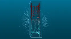
- Potential solutions for immersive cooling tank applications
- Simple on/off thresholds or continuous output
- EMI-immune performance
- Easily customizable as needed for applications
- Lowest cost
Choose an optical sensor when you need:
- Potential solutions for “Direct to chip” cooling (smaller tanks, more critical level detection)
- No moving parts
- Fast response in clean liquids
- Horizontal mounting capability
Choose an in-line flow sensor when you need:
Reliable coolant flow-related safety and control functions, including:
- Pump dry-run and prime protection
- Liquid flow indication and filter condition
- Verification of a process liquid is present before enabling a valve or heater
About the Author

Jim Dockendorff
Jim Dockendorff is Consulting Engineer for MadisonSensor. MadisonSensor manufactures high-performance fluid level sensors and float switches designed for the demanding environments of modern data centers. Learn how our solutions support reliable monitoring of cooling fluids, water management systems, and backup infrastructure to help operators maintain efficiency, prevent downtime, and protect critical assets
Voices of the Industry